Connettori per fibre ottice

Fiber Optic Connectors: Common plug types & trends


Multfiber connectors as key components in the passive fiber optic infrastructure

Technology knowledge around fiber optic connectors

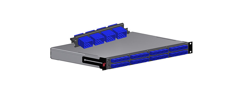
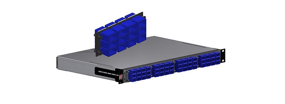
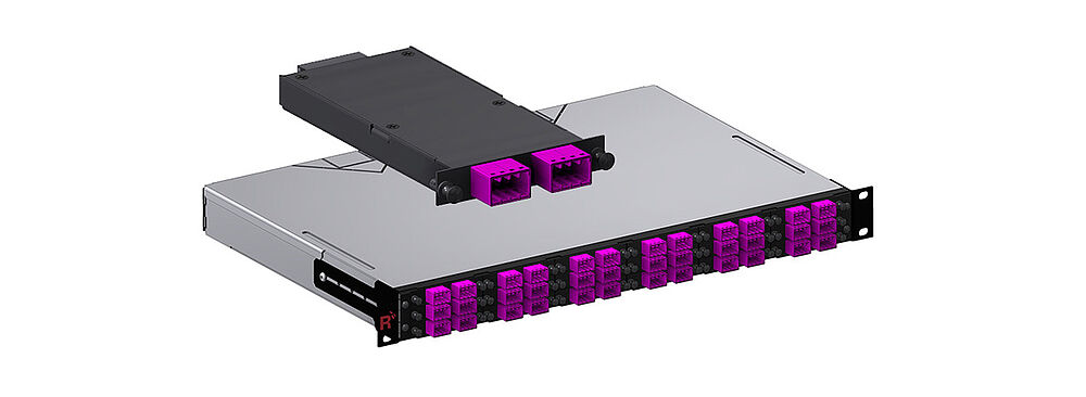
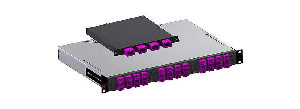
A crucial component for the performance and reliability of fibre optic transmission lines are the corresponding fibre optic connectors. Widespread connector types are: LC connector, SC connector, MTP®/MP connector, E-2000® connector. LC connectors are nowerdays most used in the market and have replaced the SC type step by step during the past few years. MTP®/MPO as multifibre connectors are mainly used within data centre infrastructures. The E-2000® find its home mainly in typical telecom wide area network environments. In addition, new designs like very Small Form Factor connectors and innovative concepts such as "Expanded Beam Optical" are approaching the market.


Fiber optic connectors with "physical contact"

As different as these above mentioned common fiber optic connectors - LC connector, SC connector, MTP®/MPO connector, E-2000® connector - look, they have a common contact principle as a basis. This principle is called physical contact. Very often appreviated as PC contact.


Contact principle & properties of PC and APC connectors

The optical fibers are fixed within a small precision ceramic pin, the so-called ferrule, and the end face is then polished during a special defined process. Inside the connector adapter, these ferrules are centered on each other and an exactly defined pressure force creates a direct physical contact between the optical fibers. Besides the tolerances of the ferrule the polishing process is highly important for the quality of the fiber connector. This principle exists in two versions: the so-called PC and APC connectors. In the PC connectors, the end faces are aligned straight against each other, while in the APC variant they are at an angle of 8 degrees to each other. APC connectors are characterized by high and stable return loss. This is an increasingly important parameter, especially for high-speed applications.


Already for many years, PC and APC connectors provide reliable performance:

  • Low insertion loss (IL)
  • High return loss (RL)
  • Stable performance over many mating cycles


The factor of cleanliness & the right way to handle fiber-optic plug connectors

However, one challenge remains: the potential contamination of the connector end face! The possible effects are a higher insertion loss - especially with singlemode fibers - as well as a reduced return loss, what in worst case can result into a total link failure. Moreover, there is a risk of permanent damage of the polished end face if they are plugged in dirty. Then the complete connector need to be replaced. For all these reasons there are comprehensive guidelines for handling fiber optic connectors. The recommended procedure can be seen here in this flow chart:


The most important thing is: PC and APC plug connectors may only be plugged in if they are absolutely clean. Therefore all fiber-optic connectors must be examined for cleanliness using a special microscope before they are plugged in. If they are contaminated in any way then they must be carefully cleaned. After this, they are checked for cleanliness again. Only when the front faces of the connectors are completely clean may they be plugged in. In some cases, this process can be quite laborious and time-intensive.


Fiber-optic connectors based on the principle of expanded beam technology

For this reason, another concept for fiber optic connectors was developed some time ago, which makes use of the expanded beam principle. Therefore they are called expanded beam connectors. Here, collimating lenses are connected in front of the ferrule or directly in front of the fiber, which expand and parallelize the light beam on one side and focus it back into the fiber on the opposite side (see figure). What does this achieve? The beam expansion significantly reduces the influence of dirt particles. In addition, there is no physical contact of the end surfaces, which reduces the risk of damage to the end surfaces by dirt.


However, this solution also brings certain disadvantages with it:

  • Relatively expensive technology
  • Relatively high insertion loss (approximately 1.5 dB)
  • Use primarily restricted to multimode applications

Due to the above-mentioned disadvantages, the concept has not yet found widespread application.


Completely new & innovative expanded beam principle

Through an extremely interesting further development of this concept, the expanded beam principle is implemented in a completely new way and with previously unknown precision. It was developed and patented by the company 3MTM and therefore also bears the name 3MTM EBO. EBO stands for expanded beam optical. Rosenberger OSI is one of the first companies to assemble the innovative 3M Expanded Beam Optical Interconnect with fiber optic cables.


By means of a new delevoped EBO ferrule the light beam is at first expanded. Afterwords on a curved surface it is divirted by 90 degrees and aligned parallel by total internal reflection. The effect is comparable to that of a collimating deflection mirror. In the opposite connector (the bottom part of the illustration) the principle is reversed and the light is coupled back into the fibre. This principle is implemented with the EBO ferrule shown here. This is a precision injection-moulded part. In the rear area it has grooves for fibre positioning instead of holes as we know it from classical PC-type connectors. The cleaved fibres are bonded  via an automated process. No polishing of fibre ends are required, what is a very unique feature. Among many others the EBO ferrule offers thus two main advantages: first it realizes an absolute new optical principle with highest precision and second it allows the possibility to automize the termination process to an extend, which was until today in case of fiber optic connectors not possible.


The illustration above shows a terminated EBO ferrule. At a defined distance from the ferrule, a so-called clamping, the collet, is attached here (Figure 1). This assembly is then inserted into a so-called cassette, which is an important part of the fibre connector (Figure 2). As already indicated the fibers are capted here with a suspension what finally supports the mating process. This mating process is shown here in 3 phases. You can see how the EBO ferrules slide over each other and finally make the optical contact. The cassette can be seen as an ideal building block for integrating the EBO technology into many other connector environments with relatively little effort.

Basic properties of the EBO plug-in system:

  • suitable for both singlemode and multimode applications
  • less sensitive to dust and dirt particels, whats makes installation and handling much easier
  • high reliability with good performance data
    - low insertion loss (IL)
    - high return loss (RL)
    - stable performance over a lot of mating cycles
  
  • low mating forces
  • flexible and scalable connector variants & options, which means it can be integrated into various connector environments 

Some connector options as an example: EBO-12 latch connector (already assembled by Rosenberger OSI)


Conclusion: In general, the EBO principle is suitable to be integrated in a lot of connector environments, but as well into active components like optical transceivers. The EBO plug-in system shows very good values and is also very stable and reliable.


3M Expanded Beam Optical (EBO) – the technology of the future for data center and industrial applications?

to the webtalk


Very Small Form Factor Connectors are on the rise

A new innovative connector that belongs to the Very Small Form Factor (VSFF) category is the MDC (stands for Miniature Duplex Connector) from US Conec. It is a true push-pull duplex connector manufactured on the basis of 1.25 mm all-ceramic ferrule technology. Designed as a Media Dependent Interface (MDI) or Optical Interface for the new SFP-DD and QSFP-DD transceivers, it has the potential to replace the LC-Duplex mass connector.


These new miniature connectors have a correspondingly smaller space requirement in the panel front due to significantly smaller dimensions compared to the successful SFF connectors (Small Form Factor) - such as the LC.

Example applications

MDC direct connection trunk - patch cable, by means of MDC coupling partial front plates

Examples of multiplication of port density per HU versus LC duplex

Within this application range, the Miniature Duplex Connector (MDC) impresses with its flexible and robust push-pull boot, which allows easy handling despite highest port densities.

> to the MDC product page

Data center cabling strategies MDC 128

PreCONNECT® SMAP-G2 UHD 19'' 1 HU 4/4 panel with 128 MDC (32 MDC 4x adapters) within the patch field, MDC 4x at trunk legs within the panel

PreCONNECT® SMAP-G2 UHD 19'' 1 HU 4/4 panel with 192 MDC (48 MDC 4x adapters) within the patch field, MDC 4x at trunk legs within the panel


Migration to Mega High Density (MHD) port density using MDC
Examples of doubling port density per HU versus LC duplex

Data Center cabling strategies GBASE SR4

40/100/200GBASE-SR4

PreCONNECT® SMAP-G2 HD 19'' 1 HU 6/6 panel with 144 (36 MDC4x adapters) within the patch field, 2 PreCONNECT® OCTO MTP 4+4F interfaces per cassette back plane

Data center cabling strategies GBASE SR8

400GBASE-SR8

PreCONNECT® SMAP-G2 HD 19'' 1 HU 3/3 panel with 144 (36 MDC4x adapters) within the patch field, 2 PreCONNECT® SEDECIM MTP 16F interfaces per cassette back plane