La connectique optique

Fiber optic connectivity systems: Expanded Beam Optical


Q&A session around the EBO principle

Our webtalk about the new Expanded Beam Optical (EBO) technology and the possibilities it offers for various applications raised very high interest. This also shows the number of questions we received after the live webtalk. That’s why we use the opportunity to interview our expert Wolfgang Rieger in a short Q&A session around the EBO principle.

Why did Expanded Beam Connectors until today not find more widespread market adoption?
As explained already during the live webtalk, former expanded beam connectors had some disadvantages (higher insertion loss, quite expensive technology). However the EBO Technology eliminates now these disadvantages, what will make the Expanded Beam concept very attractive for a lot of applications.

Is it imaginable, that the EBO technology will be integrated into active networking equipment – i.e. optical transceiver ports?
Yes, optical transceivers suffer also from contaminations with dust & dirt. We have also here concrete interest from the market, especially with regard to future 400G & 800G applications.

EBO applies the principle of expanding the beam. How much is the beam expanded in relation to the fiber core?
The beam diameter in the contact zone is about 70µm in case of Singlemode and about 200 µm in case of Multimode. However the beam diameter is not the right parameter to get a conclusion about the “in-sensivity” – it is the enlarged area which needs to be considered. I made a calculation for Singlemode and the effective area is about 60 times bigger than the Singlemode core – what means it is 60 times less sensitive.

Are there also other connector designs already available than those shown during the presentation?
Rosenberger OSI is working on projects with different companies to integrate the EBO technology into other connector designs. And also 3MTM is working on additional developments – even on additional ferrule designs.


Is there already concrete interest to apply EBO in the industrial environment?
Yes, we stated very concrete interests. We are already working on corresponding projects which will become visible soon to the market.

It is obvious, that EBO is much less sensitive versus dust particles. However, it will not work completely without cleaning. Is there special cleaning equipment required?
Of course, cleaning may be required from time to time – however that’s quite easy. Normal particles can be removed just by blowing compressed air over the ferrule. Some standardized dust tests were done – also in comparison to MTP®/MPO connectors. And EBO is much easier to clean & to keep clean than the MTP®/MPO.

How is the current market acceptance / adoption for the EBO technology?
EBO is in fact a brand-new technology and it is normal that it will take time, till the market will recognize the value and benefit of such new technologies. But there is already good progress, because we see real high interests from various sides.

You still have any open questions about the EBO technology that we didn’t answer yet? Don’t hesitate to contact us! If you missed our live webtalk discussing the question if the EBO technology will be the future in datacenters and industrial applications check it out here.


3M Expanded Beam Optical (EBO) – the technology of the future for data center and industrial applications?

to the Webtalk


The completely new innovative "Expanded Beam" principle

It was developed and patented by the company 3MTM and has therfore the name 3MTM EBO. EBO stands for Expanded Beam Optical. With regard to this new technology Rosenberger Optical Solutions & Infrastructure (Rosenberger OSI) entered already in an early stage into a close cooperation with 3MTM. The Expanded Beam priciple is implemented here in a complete new way and with a precision not known until know.


Functionality and advantages

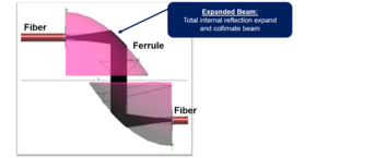
By means of a new delevoped EBO ferrule the light beam is at first expanded. Afterwords on a curved surface it is divirted by 90 degrees and aligned parallel by total internal reflection. The effect is comparable to that of a collimating deflection mirror. In the opposite connector (the bottom part of the illustration) the principle is reversed and the light is coupled back into the fibre. This principle is implemented with the EBO ferrule shown here. This is a precision injection-moulded part. In the rear area it has grooves for fibre positioning instead of holes as we know it from classical PC-type connectors. The clieved fibres are bonded  via an automated process. No polishing of fibre ends are required, what is a very unique feature. Among many others the EBO ferrule offers thus two main advantages: first it realizes an absolute new optical principle with highest precision and second it allows the possibility to automize the termination process to an extend, which was until today in case of fiber optic connectors not possible.


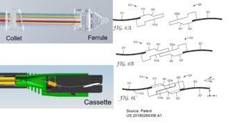
The illustration above shows a terminated EBO ferrule. At a defined distance from the ferrule, a so-called clamping, the collet, is attached here (Figure 1). This assembly is then inserted into a so-called cassette, which is an important part of the fibre connector (Figure 2). As already indicated the fibers are capted here with a suspension what finally supports the mating process. This mating process is shown here in 3 phases. You can see how the EBO ferrules slide over each other and finally make the optical contact. The cassette can be seen as an ideal building block for integrating the EBO technology into many other connector environments with relatively little effort.

What kind of performance can be expect from this fibre optic connectivity system?
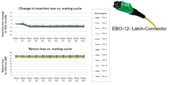
The "Expanded Beam" concept offers impressive values in the areas of insertion loss (IL) and return loss (RL) (see illustration). It is quite close to the one of classical PC or APC-connectors. The maximum insertion loss specified for the EBO system is 0.7 dB for singlemode and 0.3 dB for multimode. The typical values are in the range of 0.3 - 0.4 dB for singlemode and approx. 0.2 dB for multimode. And also the return loss is in a range how it is required for today's and future high-speed applications.

But what is perhaps even more important: this system is characterised by excellent repeatability and stability over many mating cycles (see figure below). The upper diagram shows the change in insertion loss and the lower diagram the return loss, both over 100 mating cycles.


Conclusion: The EBO connectivity system shows very good absolute values and is also very stable and reliable.
A summary of the basic properties of the EBO plug-in system:

  • suitable for both singlemode and multimode applications
  • less sensitive to dust and dirt particels, whats makes installation and handling much easier
  • high reliability with good performance data
    - low insertion loss (IL)
    - high return loss (RL)
    - stable performance over a lot of mating cycles
  • low mating forces
  • flexible and scalable connector variants & options, which means it can be integrated into various connector environments 

Some connector options as an example::

  • EBO-12 latch connector (already assembled by Rosenberger OSI)
  • EBO-24 latch connector
  • prototype of a backplane connector with 192 fibres

In general, the EBO principle is suitable to be integrated in a lot of connector environments, but as well into active components like optical transceivers.

> to the EBO product page